Key Takeaway:
The four conventional NDT methods for welds are UT, RT, MT, and PT, each suited to different defects. The right call depends on defect location, material, and how much of a record the project needs, and code-driven inspection often combines methods rather than picking one. When surface access is restricted or the assembly is complex, 3D Computed Tomography extends the volumetric view beyond what UT and RT can resolve. At PTS, our Singapore laboratory is accredited to ISO/IEC 17025:2017 by SAC-SINGLAS and handles all four methods plus 3D CT under one roof.
Table of Contents
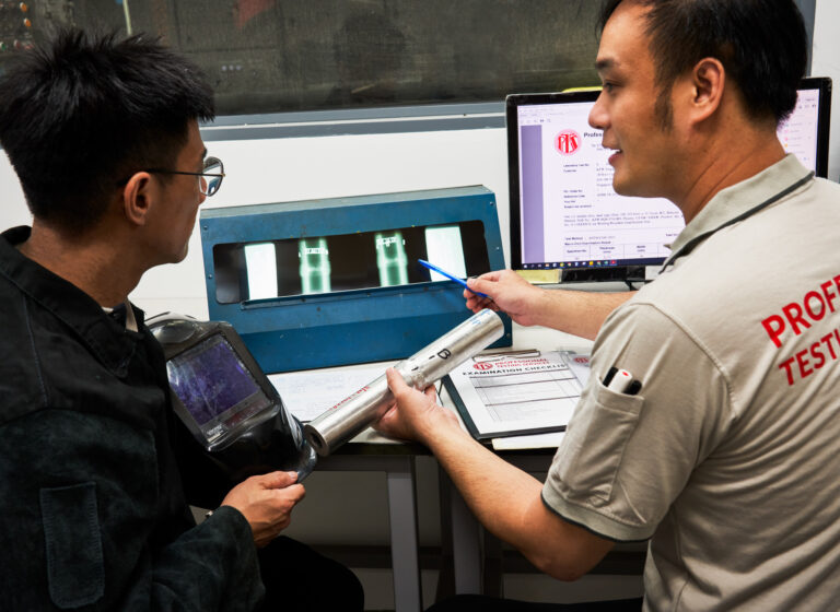
A suspected crack in a weld is one of the most stressful calls a QA engineer takes. The next question is always the same. Which NDT method actually finds it? The answer shifts with the defect type, the material, the geometry, and how much of a record the project needs to keep.
Below, we cover the four conventional NDT methods, what each one detects, and how to match the right one to the job for structural and pressure welds across Singapore and Malaysia. When conventional methods reach their limit, we cover the volumetric option that picks up where they leave off.
The Four Conventional NDT Methods for Welds
Before matching a method to a defect, it helps to know what each one does. The difference between ultrasonic testing and radiographic testing gets the most attention, but MT and PT are just as important in the daily inspection toolkit.
- Ultrasonic Testing (UT): High-frequency sound waves detect subsurface and volumetric defects. Strong on thick sections and in-service inspection where access is single-sided.
- Radiographic Testing (RT): X-ray or gamma imaging produces a permanent film or digital record. Best for volumetric defects like internal porosity, slag inclusions, and lack of fusion in butt welds.
- Magnetic Particle Testing (MT): Picks up surface and near-surface indications on ferromagnetic materials only. Fast, portable, low cost.
- Dye Penetrant Testing (PT): Surface-breaking defects only, but works on non-porous materials of any type, including stainless steel and aluminium. Easy to deploy in the field.
What Each Method Detects and Misses
Each method reads certain defects well and misses others, making it useful to know which is which before the coupon leaves the site.
- Surface cracks: MT (ferromagnetic) and PT (any non-porous material) find these reliably. UT and RT can miss shallow surface indications.
- Subsurface cracks: UT is the standard call, especially for thick sections. These are planar defects, so RT catches them only when they lie favourably to the beam. Tight defects perpendicular to the film often go undetected.
- Porosity, slag, and lack of fusion: RT reads these clearly on the radiograph. UT can also detect them, though interpretation takes more skill.
- Lack of penetration in a full-penetration joint: RT and UT both work. RT gives the visual record that most codes want on file.
Two other factors narrow the choice. First, material and access constraints:
- MT works on ferromagnetic material only, so it is off the table for austenitic stainless and aluminium.
- RT brings radiation exclusion zones that need planning around on a live site.
- UT needs a competent operator and a couplant on the surface.
- PT only reveals what breaks the surface.
Second, cost and turnaround, which follow a rough order: PT and MT are the quickest and cheapest, UT sits in the middle, and RT tends to take longest because of safety controls and film processing or digital review.
Decision Framework: Matching the Method to the Defect
Defect and material | Method to reach for |
Surface-breaking crack, carbon steel (ferromagnetic) | MT first, PT as a backup or where MT is not practical |
Surface-breaking crack, stainless or aluminium (non-ferromagnetic) | PT, since MT will not work on non-ferromagnetic material |
Subsurface crack or lack of fusion, thick section | UT, with phased array where geometry is complex or sizing accuracy matters |
Internal porosity or slag in a butt weld | RT |
Incomplete penetration in a full-penetration joint | RT or UT |
Critical component needing a permanent volumetric record | RT, with UT as a complementary check for tighter planar defects |
Combining methods is standard practice for code-driven inspection. AWS D1.1, for example, allows MT or PT for surface indications alongside UT or RT for internal ones on structural welds. ASME BPVC Section V sits behind this, setting out the procedural requirements for each NDT method used on code equipment.
When Conventional NDT Isn't Enough
Every method has a ceiling. Complex geometries, multi-material assemblies, or components where surface access is restricted push UT and RT to their limits.
When defect sizing needs to be more precise than a 2D radiograph allows, or when the internal path of a weld through a machined part matters, 3D Computed Tomography extends the volumetric view. CT reconstructs the full internal structure and lets you cross-section the part at any angle in software. It sits above conventional NDT for high-value or safety-critical parts, not as a replacement for routine weld inspection.
How We Support Weld Inspection at PTS
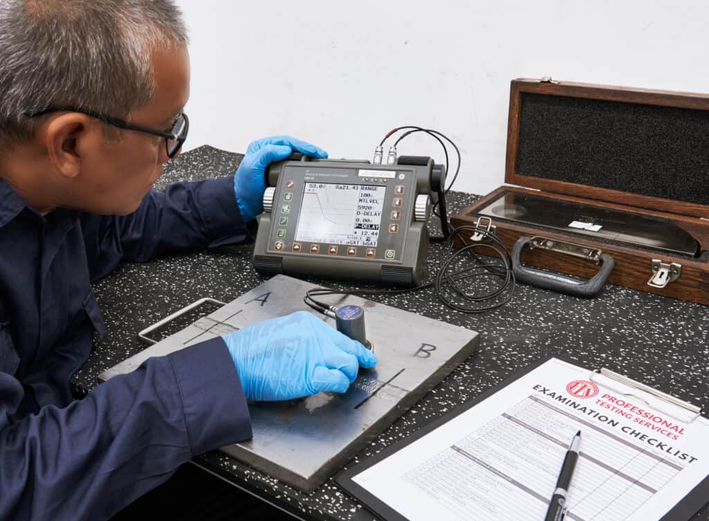
We are a material testing lab in Singapore operating since 1985, with facilities in Singapore, Malaysia, and Indonesia. Our laboratory is accredited to ISO/IEC 17025:2017 by SAC-SINGLAS, and our scope covers NDT alongside mechanical, chemical, and metallurgical testing.
All four conventional NDT methods run under one roof, so we can recommend the right combination for a given weld inspection scope rather than defaulting to one method. Our reports and turnaround are geared to project deadlines on structural, offshore, and pressure equipment work, and where the geometry demands it, we can escalate to 3D CT within the same laboratory.
Choose the Right NDT Method with Us
Catching a weld crack comes down to matching the method to the defect. UT, RT, MT, and PT each have a specific job, and combining them is often the right call for code-driven inspection. When conventional NDT hits its limit on complex geometries or safety-critical parts, 3D CT extends the volumetric view.
At PTS, we give Singapore and Malaysia fabricators access to all four conventional NDT methods plus 3D CT under one accredited testing laboratory. Our ISO/IEC 17025:2017 accreditation by SAC-SINGLAS covers our NDT scope, so weld inspection reports carry the credibility that structural, offshore, and pressure work demands.
References:
ISO/IEC 17025:2017 — General requirements for the competence of testing and calibration laboratories. Retrieved 4 September 2026, from https://www.iso.org/standard/66912.html
SAC Accreditation Schemes — Laboratory Accreditation Scheme (SAC-SINGLAS). Retrieved 4 September 2026, from https://www.sac-accreditation.gov.sg/
AWS D1.1/D1.1M: Structural Welding Code — Steel. Retrieved 4 September 2026, from https://www.aws.org/standards-and-publications/codes-and-standards/d1-1/
ASME Boiler and Pressure Vessel Code, Section V — Nondestructive Examination. Retrieved 4 September 2026, from https://www.asme.org/codes-standards/find-codes-standards/bpvc-v-bpvc-section-v-nondestructive-examination
Frequently Asked Questions About NDT for Weld Crack Detection
It depends on where the crack sits and what material the weld is on. For surface-breaking cracks on carbon steel, magnetic particle testing (MT) is the first call, with dye penetrant testing (PT) as a backup. For stainless steel or aluminium, PT is used because MT will not work on non-ferromagnetic materials. For subsurface cracks in thick sections, ultrasonic testing (UT) is the standard. For internal porosity, slag, or lack of fusion in a butt weld, radiographic testing (RT) is the go-to. Many code-driven inspections combine two methods.
UT uses high-frequency sound waves to detect subsurface indications and is well suited to thick sections and single-sided access. RT uses X-ray or gamma radiation to produce a permanent image of the internal weld and is stronger for volumetric defects like porosity, slag, and lack of fusion. UT is often faster and cheaper. RT gives a documented record that codes and clients frequently ask for on critical welds.
3D Computed Tomography is the right call when the geometry is too complex for UT and RT to resolve clearly, when a component has restricted surface access, or when precise defect sizing matters. It is not a replacement for routine weld inspection. It sits above conventional NDT for high-value or safety-critical parts where the internal structure needs to be reconstructed and cross-sectioned digitally.
Yes. PTS’s laboratory is accredited to ISO/IEC 17025:2017 by SAC-SINGLAS. The accreditation covers our NDT scope alongside mechanical, chemical, and metallurgical testing. Individual methods within our NDT scope, including UT, RT, MT, and PT, fall under this accreditation for weld inspection work.
CONTACT US TODAY
We offer non destructive testing for welding across Singapore and Malaysia, backed by four decades of inspection experience in marine, oil and gas, and structural work. If you are specifying NDT testing in Singapore for a project and need an accredited lab that can execute the full scope in one place, our team is ready to scope it with you.