Key Takeaway:
- Industrial CT scanning is a non-destructive imaging method that produces complete 3D volumetric models of a component’s internal and external geometry.
- The process works by capturing hundreds to thousands of X-ray projections as a part rotates, then reconstructing those 2D images into a navigable 3D model using algorithms like filtered back projection.
- Each voxel (3D pixel) in the reconstructed model holds density information, allowing engineers to distinguish between different materials, detect voids, and measure internal features.
- Industrial CT serves multiple QC functions: NDT defect detection, dimensional metrology, first article inspection, failure analysis, reverse engineering, and assembly verification.
- When evaluating CT service providers, key considerations include ISO/IEC 17025 accreditation, equipment capability (resolution, part size limits), turnaround time, and technical support for interpreting results.
Table of Contents
Industrial CT scanning has become a core tool for quality control, failure analysis, and dimensional verification across manufacturing sectors. But the principles behind it and how does industrial CT scanning work at a technical level may not be immediately clear to most engineers and technical directors. What data does it produce? What are its limitations? And how does it compare to other inspection approaches?
If you’re wondering about the CT scanning data acquisition process, let’s walk you through the core steps, its applications, how industrial X-ray inspection works, its comparison with 2D radiography, and what to look for when evaluating a service provider.
What Is Industrial CT Scanning?
Industrial computed tomography (CT) is a non-destructive imaging technology that captures the full internal and external geometry of a component and renders it as a 3D volumetric model. Unlike surface-only scanning methods, CT produces data on everything inside the part: material density, voids, inclusions, internal channels, and assembled components.
The operating principle is similar to medical CT, but industrial systems typically use higher X-ray energy levels to penetrate dense materials like metals, composites, and ceramics to achieve finer resolutions, sometimes down to the sub-micron level, which is critical for inspecting small or complex components.
The key output of the scan is a voxel-based 3D model. Each voxel (a volumetric pixel) contains density information, giving engineers a complete, measurable dataset of the scanned object’s internal structure. This goes well beyond what surface scanning or traditional 2D X-rays can provide.
The Core Principle: X-Ray Attenuation
At the heart of CT scanning is a straightforward physical principle: X-ray attenuation. When X-ray beams pass through an object, different materials absorb (attenuate) the radiation at different rates depending on their density and composition. Dense materials like steel or copper absorb more X-rays than lighter materials like plastic or aluminium, resulting in different levels of signal reaching the detector.
These differences in absorption are recorded as variations in grey values on the detector image, with high-density areas appearing brighter and low-density areas appearing darker. This contrast is what allows CT to distinguish between different materials, identify voids or air gaps, and detect inclusions or foreign material within a component.
During a scan, this attenuation data is captured across hundreds or thousands of angles as the part rotates on the scanning stage. The accumulated data from all these angles form the basis for reconstructing a full internal map of the object.
CT Scanning Data Acquisition Process
The CT scanning data acquisition process follows a structured sequence. Here is a step-by-step breakdown of how 3D X-ray computed tomography captures and processes data.
1. Setup & Positioning
The process begins with defining the inspection objectives. Scan parameters are determined based on what you are looking for: voids, cracks, dimensional data, assembly verification, or other.
The part is placed on a rotating stage, positioned between the X-ray source and a flat-panel detector. The source energy, detector distance, and resolution settings are configured based on material density, part size, and the level of detail required to get the right parameters for producing usable data.
2. Projection Capture
The X-ray source emits a cone beam that passes through the part and strikes the detector, producing a 2D radiograph (essentially a shadow image of the internal structure). The part then rotates incrementally, typically through a full 360°, with the system capturing a new projection at each angle.
A single scan can produce anywhere from several hundred to several thousand individual projections, depending on the objective of the scan and resolution requirements.
3. Data Reconstruction
Once all projections are captured, reconstruction software compiles the 2D images into a 3D volume. The industry-standard approach is filtered back-projection (FBP), though iterative reconstruction methods are also used when scan data is limited or higher fidelity is needed.
The result is a voxel-based 3D model where each voxel holds a grey value corresponding to the material density at that specific point. Engineers can slice through this model in any plane, rotate it, zoom into specific regions, and inspect internal features that would be impossible to reach physically without disassembly.
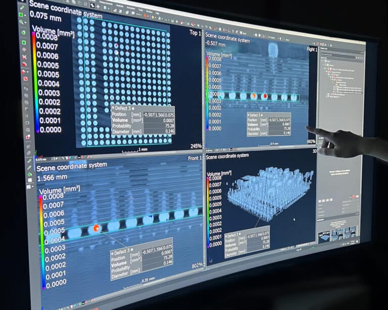
4. Analysis & Output
With the 3D volume reconstructed, analysis can begin. Common outputs include slice-by-slice visual inspection, automated porosity and void detection, dimensional measurements, and CAD comparison for deviation analysis. This data can then be exported for QC reporting, further engineering analysis, or integration into broader quality management systems.
Industrial CT vs 2D Digital Radiography
Engineers evaluating inspection methods often weigh CT against 2D digital radiography (DR). Both use X-ray technology, but they serve different purposes and operate at different levels of detail, so it’s important to understand how industrial X-ray inspection works across both methods to select the right approach for a given application.
- 2D Digital Radiography captures a single-plane X-ray image of the internal structure. It is faster and has a lower cost per scan, making it well-suited for detecting cracks, voids, and inclusions in simpler geometries. 2D DR is commonly used for quick pass/fail assessments and high-volume inspection workflows. A typical example is digital radiography pipe inspection for weld integrity verification, where speed and throughput are priorities.
- 3D CT Scanning produces full volumetric data covering both internal and external geometry. It is better suited for complex parts, multi-component assemblies, and applications requiring precise defect location, dimensional measurement, or CAD comparison. Scan times and costs are higher, but the data output is far more comprehensive.
In practice, these methods are not always mutually exclusive. Many QC workflows use both: 2D DR for initial screening and high-volume throughput, and 3D X-ray computed tomography for detailed analysis of critical components or when a failure investigation demands full volumetric data.
Common Applications in Quality Control
Industrial CT scanning supports a range of QC functions. Here are the most common applications that an industrial CT scan Singapore service provider (like PTS) typically handles:
- Non-Destructive Testing (NDT): Detect voids, porosity, cracks, and inclusions. Verify component placement in sealed assemblies without disassembly.
- Metrology & Dimensional Analysis: Measure internal and external dimensions from CT data and compare against CAD models for deviation checks.
- First Article Inspection (FAI): Validate new parts against design specifications before production approval, capturing complete geometry in a single scan.
- Failure Analysis: Locate internal defects that caused field failures and identify the root cause without destroying the physical evidence.
- Reverse Engineering: Generate 3D models from physical parts with no existing CAD data, which is particularly useful for legacy components or obsolete parts.
- Assembly Verification: Confirm that internal components are correctly positioned, and detect missing parts, misalignments, or foreign object debris.
Industry Applications
The question of how does industrial CT scanning work in practice varies by sector, but the core technology applies across a broad range of industries:
- Aerospace & Defence: Turbine blades, castings, avionics housings, composite structures. These are high-stakes components where internal defects are unacceptable, and inspection requirements are stringent.
- Automotive: Engine components, sensors, EV battery packs, die-cast parts. CT supports both production QC and lightweight design R&D.
- Electronics: PCBs, connectors, solder joints, micro-assemblies. CT detects voids, shorts, and placement errors at a scale that visual inspection cannot reach.
- Medical Devices: Implants, surgical instruments, sealed devices. CT verifies internal integrity without compromising sterility or packaging.
- Additive Manufacturing: 3D-printed metal and polymer parts. CT identifies porosity, incomplete fusion zones, and deviations in internal geometry from the original design file.
Oil & Gas: Valves, fittings, pipe welds. CT supports asset integrity programmes and failure investigations, often alongside digital radiography pipe inspection for routine weld screening.
What to Look for in a CT Service Provider
For engineers and technical directors evaluating 3D X-ray computed tomography service providers, a few practical criteria help separate capable labs from those that may fall short:
- Accreditation: ISO/IEC 17025 is the baseline standard, confirming that the lab operates under a recognised quality management system and produces technically valid results.
- Equipment capability: Check maximum scannable part size, achievable resolution, and the range of material densities the system can handle.
- Turnaround time and reporting format: Understand typical lead times and whether output formats align with your QC workflow (e.g., exportable 3D data, deviation maps, pass/fail summaries).
- Technical support: CT data requires interpretation. A strong provider offers guidance on scan parameters and results analysis on top of providing scan data.
Partner with PTS for CT Scanning Services
The CT scanning data acquisition process might seem complex, but the core of how industrial X-ray inspection works lies in scanning a given material with attenuated X-rays to create valuable reconstructed volumes. With that understanding, you can then select an inspection approach and service provider that best fits your quality objectives.
Professional Testing Services (PTS) has operated as an independent test laboratory since 1985. As an ISO/IEC 17025:2017-accredited laboratory, we offer industrial CT scan services in Singapore alongside digital radiography pipe inspection and comprehensive non-destructive testing capabilities. With our laboratories in Singapore, Malaysia, and Indonesia, plus an office in Brunei, we support manufacturers and engineering teams across the region with fast turnaround, reliable results, and hands-on technical guidance.
References:
- ISO – ISO/IEC 17025 — Testing and calibration laboratories. (date n/a). International Organization for Standardization. Retrieved on 25 February 2026 from https://www.iso.org/ISO-IEC-17025-testing-and-calibration-laboratories.html
Frequently Asked Questions About Industrial CT Scanning
Both use the same core principle of X-ray attenuation and reconstruction, but industrial CT systems operate at higher energy levels to penetrate dense materials like metals and composites. Industrial scanners also achieve finer resolutions (down to sub-micron levels in some systems) and use a rotating stage rather than rotating the source and detector around a stationary subject.
Industrial CT can scan a wide range of materials, including metals (steel, aluminium, titanium, copper), polymers, ceramics, composites, and multi-material assemblies. The key constraint is material density relative to X-ray energy: very dense or very thick metal sections may require higher-energy systems or adjusted scan parameters to achieve adequate penetration and image quality.
Accordion Content
Scan time varies depending on part size, material density, and the resolution required. Simple scans of small, low-density components may take under 30 minutes. Complex scans of larger or denser parts requiring high resolution can take several hours, including setup, calibration, scanning, reconstruction, and post-scan analysis.
CT is generally the better choice when you need full volumetric data, precise defect location in three dimensions, dimensional measurement, or CAD comparison. 2D digital radiography is more suited for high-volume screening, simpler geometries, or applications where a single-plane image provides sufficient information for pass/fail decisions. Many QC programmes use both methods at different stages of the inspection workflow. If you’re unsure of which to choose between 2D radiography and 3D CT, talk to our CT specialists today, and we’ll help you find the best solution for your project.
Talk to us today
Reach out to PTS today to discuss your inspection requirements, or witness the potential of industrial CT scanning with our complimentary first scan for new customers.


